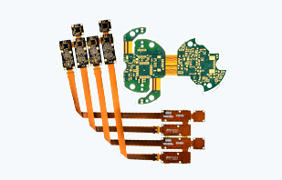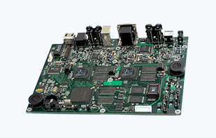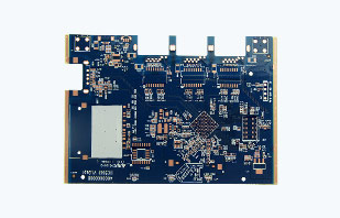
The Expense Contrast of Rigid Flex PCB and typical PCB

Relocating to a rigid flex PCB design from the conventional approach of using cable assemblies to join two or even more PCB’s has evident benefits consisting of:
the ability the match a smaller kind factor, less weight, enhanced transmission capacity and boosted existing lugging capabilities.

A common question that we are asked is how you can contrast the price of a rigid flex PCB with the standard approach.

Usually, if you look only at the PCB expense, a rigid flex PCBconstruction is mosting likely to be a lot more pricey. Yet after assessing the general cost of the assembly, very often there is an expense financial savings.

The complying with listing is not meant to be extensive. Every application will certainly be unique. Our hope is that this listing aids promote the thought process when doing a contrast of the two innovations.

Things to think of when contrasting the overall cost of an assembly:

You are merging multiple boards into 1 design
Rigid PCB’s.
Wire.
Cost of wires and adapters.
Diminish Tubing.
Connectors.
Wire Ties.
Cable Pens.
Freight.

Cost of the assembly procedure. You can currently run one assembly as opposed to 2 or 3.
Human Labor.
Cable Assembly Test.
Kitting for assembly.
In Process Evaluation.
PCB Tooling/Test.
On Board/ Last Test.
Misc. costs– engineering time, and so on

.
Examining:. Possibility of one test operation AND the capability to evaluate the full assembly prior to installation.

Reliability.
No solder connections in between boards.
Reliability comes from a good design.
The flex adapter is currently an essential part of the board.
Order Processing Prices.
Obtaining.
Incoming Evaluation.

Order generation.
Material Storage space.

As I stated, this checklist is far from complete and meant to set off conversation on the costs of an overall assembly. We are constantly here in order to help answer any type of questions or offer added info on both cost contrasts and rigid flex PCB design. extra information, please see our site at www.ifastpcb.com.

Flex PCB & Rigid Flex PCB mechanical designs

This short article is meant to apply the design support we offer at iFastPCB in regards to our flex PCB and rigid flex PCB. Technical design and design is one of our core principles that permits us to assist our customers satisfy there product requirements. The short article will cover design locations that require unique factor to consider.

Preliminary Rigid Flex PCB Design Principle

Obtaining associated with a design at the theoretical degree can be an advantage for both the PCB manufacturer and the OEM. When it concerns flex and rigid flex PCB circuits it is essential to understand the full job demands ahead.

The process begins with a conversation. This typically includes a call with the client’s project monitoring and design groups in order to help develop a first understanding of all the information.

Design Factors We Should Know Are:

-Are there any type of special signal requirements such as impedance control and or current carrying needs?
-Exactly what is the basic component shapes and size?
-What is the functionality of the flexible PCB?
-Exist other variables such as a radio frequency design (RF)? Is shielding needed due to the atmosphere it will be running in?
-Just what are they aiming to achieve and just what do they need to achieve?
-Is the design an indicate point adjoin or an energetic element?
-All these inquiries aid us suggest about what your demands are.
-The number of interconnects are there mosting likely to be? Even more interconnects boosts the intricacy.
-Throughout this process we additionally begin feeding information back to you to give you a clearer understanding of flex and rigid-flex modern technologies that may pertain to your requirements.

All of these considerations assist us figure out if a flex PCB solution is even valid for your application. Sometimes we might concern the final thought that it may not be plausible to utilize a flexible circuits board ultimately product’s design. We are always aiming to maintain your best interests in mind and will certainly not develop something just for the benefit of developing it.

We likewise try to determine added levels of performance that can be integrated into the design. We search for higher levels of assimilation in between the separate parts. In many cases we even should simplify to decrease levels of combination that are not needed and are overly complex, which could consequently supply expense decreases.

Mechanical Design

Once we have completed the design principle stage and identified that a flex and rigid flex PCB is a valid remedy, we after that begin to check into even more of the specific information of the mechanical design.

Some things that we have to understand are:

-From a PCB manufacturing perspective we start checking out the sizes and shape of the flex PCB part. Not all shapes and arrangements are manufacturable because of the distinct PCB manufacturing processes that are run into in flex and rigid flex PCB manufacturing.

-Just what are the minimum bend requirements? Just how are you going to be bending the flex PCB into position? What are the flex section lengths required to meet the bend demands? These are needed to protect against trace damage once the component is being used in the long run product.
-We love to notify clients on added mechanical design elements that we could offer the table. We do however understand that most of our consumers are familiar with rigid PCB.
-Remember that not all sizes are available. Large components can develop technological difficulties due to the dimensional stability of the materials themselves in addition to the PCB manufacturing resistances that can develop. You could have the ability to design it, yet it’s not always manufacturable.

Various other Mechanical Design Aspects:

-PSAs, which are generally dual sided tapes made use of to attach the flex within the unit.
-Stiffeners, which are called for to support soldered adapters and parts to make sure integrity.
-Exist any type of protecting needs if the design is an RF or EMI sensitive application? This can be finished with various methods such as copper layers, silver Ink layers, or special shielding films. Each of these has their very own strengths and weak points which ought to be reviewed relying on the job.
– Exist any special PSA requirements such as a heat setting? Do you need the PSA to be thermally conductive to dissipate heat? Does it should be electrically conductive to ground the component to the unit?

Does the flex PCB circuit need any type of epoxy stress alleviations, which come into play if there is going to be a bend close to a stiffener or to the rigid PCB section? This might need a grain of epoxy at that interface to avoid to circuit traces to break.

Summary

In summary, not all flex and rigid flex layouts are produced equal. Comprehending all of the discussed aspects will aid identify exactly what the most effective feasible solution will certainly be for your end product. If you are seeking additional details or call for aid to establish if a flex PCB service is the most effective option for you, please feel free to contact us to ask for even more info on our flex and rigid flex PCB manufacturing service.

Rigid flex PCB manufacturers plan for wearables market

Deliveries of wearable gadgets worldwide will rise by 43 percent between 2014 and 2019. This means a more comprehensive application base for rigid flex PCB boards.

From medical and army tools to the warm mobile phones, rigid flex PCB manufacturers in China are targeting potential customers in the possibly big wearables market. Global deliveries of such products are projected to skyrocket at 43 percent CAGR in 2014-19, according to IDC.

By device, the total amount will certainly hit 173.4 million at the end of the period from 28.9 million in 2014, providing one more application chance for the hybrid PCB category.

Presently, smart devices, laptop computers and tablet Computers are the crucial markets for this PCB board, yet mainland China PCB manufacturers have now alloted a portion of their PCB outcome for worn digital devices. The application’s share at iFastPCB, which started supplying rigid flex PCB boards in 2015, is about HALF.

Boasting the consolidated benefits of rigid and flex PCB boards, this PCB kind has the included benefit of room and weight reduction. This is since its building and construction eliminates the demand for adapters, cords and bow cable televisions in styles calling for numerous PCBs. Enhanced efficiency and integrity are also the variant’s forte as a rigid flex PCB can be bented, folded up and rolled, making them proper for wearables produce.

Some PCB manufacturers are working to update their options for this market too. They highlight HDI kinds, which surpass traditional multilayer designs in circuit thickness. Mainland China PCB manufacturers such as iFastPCB could turn out such sophisticated PCBs.

The rigid flex PCB group is still a minority in the local PCB sector. It makes up less than 5% of iFastPCB return. PCB manufacturers are positive the broadening application base and resulting increase in requirement will certainly sustain more than 10 percent development in sales annually.

Production of rigid flex PCB is focused in Europe, North America and Asia, with the initial two areas churning out variants primarily used in the military/aerospace, medical and automotive electronic devices areas. Asia, on the other hand, concentrates on the consumer electronics market.

For the mainstream multilayer segment, domestic providers continue to stress better circuit thickness to keep up with the trends for miniaturizations and multiple features in terminal applications. Higher layer matter, tighter line width and spacing and reduced hole dimensions stay as purposes. At present, the variety contains 3 to 12-layer options with 1.4 mil being the minimum in line size and spacing, and 0.1 and 0.05 mm openings specifically via mechanical and laser boring.

In the landmass, there are more than 100 PCB manufacturers of the PCB kind, of which one-third are domestic ventures. The remainder includes foreign-invested business such as Compeq, Unitech and Career. Virtually half of this swimming pool runs in Guangdong district, especially in the cities of Shenzhen and Dongguan.

Typical products
Multilayer devices comprise the bulk of rigid flex PCB manufacturing in the mainland, although PCB manufacturers continue to supply solitary- and double-sided types. No matter classification, these boards take on FR-4 base materials for the rigid component and polyimide or PET DOG for the flexible PCB section. ENIG, OSP, and immersion tin, silver and gold are utilized for the surface area finish.

China PCB manufacturers obtain CCL and FCCL in your area and from Taiwan. The vital resources of the previous material consist of Nanya, Iteq, GDM, Shengyi and EMC. The second in 3L and the extra commonly made use of 2L kinds originate from Taiflex, Shengyi, Elegance, ThinFlex and Microcosm. For solder mask, Goo, Taiyo, Tamura and GreenCure are the significant international carriers.

Mainstream 3-layer systems have 2R +1 F configuration, 4-layer 2R +2 F, 5-layer 2R +1 F +2 R, 6-layer 2R +2 F +2 R and 10-layer 4R +2 F +4 R. In regards to minimal line width and spacing, those with 2, 3 and 4mil are a lot more typical than versions with 1.4 and 1.6 mil. By hole sizes, as big as 0.3 mm to as tiny as 0.05 mm are the selections.

iFastPCB supplies 2 to 6-layer versions with 3mil as the very least line size and spacing and 0.2 mm openings. Leading Electronic’s up to 10-layer choice has 3mil and 0.1 mm as minimum criteria.

Material expense is stable and will certainly help rigid flex PCB manufacturers preserve costs in the middle of climbing labor expense

New Cadence Allegro System Accelerates the Design of Rigid Flex PCB Applications

On Could 3rd at CDNLive EMEA, Tempo nveiled the Allegro ® 17.2-2016 profile, which enables a more predictable and shorter design cycle. The portfolio showcases extensive in-design inter-layer checking modern technology that lessens design-check-redesign iterations and a new dynamic simultaneous group design ability that speeds up product creation time by up to HALF. Making use of material inlay fabrication methods, these new abilities can minimize material costs by as much as 25 percent. Furthermore, embedded SigrityTM technology currently guarantees important signals meet efficiency requirements and power stability (PI) for PCB developers dealing with power delivery and IR-drop concerns successfully, getting rid of taxing models with PI specialists.

The Allegro portfolio consists of key advancements that minimize design models and reduced general cost for flex PCB and rigid flex PCB designs commonly utilized in vehicle, customer electronic devices, computer, interactions, mobile and wearable applications. These capabilities include:

-. One-of-a-kind and detailed in-design inter-layer look for rigid flex PCB that saves manual effort and guarantees all regulations for breakthrough flex PCB layouts are abided by, preventing lots of design-check-redesign models.

-. PI for Rigid Flex PCB designers that leverages Allegro and Sigrity modern technologies to provide faster, much more reputable access to IR-drop evaluation outcomes, allowing the PCB designers to efficiently meet power distribution network (PDN) design requirements.

-. The Allegro profile currently supplies concurrent team design ability, which could reduce design time by as much as 50 percent for thick designs and increase efficiency by making it possible for the group to design synchronously. This feature enables PCB developers to achieve optimum productivity by enabling up to 5 PCB designers to conduct real-time, concurrent PCB design job within the very same design database, shortening time to path a thick design by up to 80 percent.

-. Rigid Flex PCB design improvements that give designers the capability to define multiple rigid and flex stack-ups in the same data source. This stack-up-by-zone function can additionally be used in rigid styles to create material inlay areas leveraging a mix of pricey and economical materials, enabling reduction of material price by up to 25 percent.

-. New Indigenous 3D engine that simplifies the system design process and offers improved visualization and crash discovery to prevent unnecessary MCAD/ECAD versions.

-. Interoperable Allegro and Sigrity innovations that provide an easy to use setting, which reduces design and confirmation time. This is accomplished by staying clear of unneeded physical PCB prototype iterations through boosted route channel usage using tabbed routing, new in-design backdrilling rules and effective sharing of custom return course via frameworks optimized with Sigrity modern technology.

” Due to the nature of our business, flex PCB designs are extremely important to most of our products, especially in the mobile and automotive area. The breadth and the depth of enhancements have the ability to dramatically boost our PCB design efficiency in making for space-constrained applications,” stated Greg Bodi, supervisor of System Engineering PCB Layout, Nvidia. “The brand-new inter-layer check capacity supplies comprehensive in-design, real-time checks, which will certainly save us significant time currently invested doing hand-operated checks after layout is finished on advancement flex PCB and rigid flex PCB layouts.”

” The current Allegro release provides numerous productivity and convenience of use enhancements,” stated Dave Elder, PCB Design supervisor at Tait Communications. “In-design inter-layer checks for flex PCB and rigid flex PCB design is detailed and extensible, which can save us 20 to 25 percent time for rigid-flex designs. This will certainly also permit us to retire some organic remedies we established.”

” The new Allegro system addresses many difficulties dealt with by PCB developers on a daily basis,” claimed Saugat Sen, vice president of R&D, PCB and IC Product packaging Team at Cadence. “We remain to offer market-leading options with Allegro’s comprehensive Rigid Flex PCB capacities coupled with industry-leading power conscious Sigrity SI/PI innovation to reduce design cycle time for our consumers’ compact, high-performance products.”

About Tempo
Cadence enables global electronic design advancement and plays a crucial role in the creation these days’s integrated circuits and electronic devices. Clients make use of Tempo software application, equipment, IP and solutions to design and validate advanced semiconductors, customer electronics, networking and telecom tools, and computer system systems.

Introduction to Rigid Flex PCB Manufacturing

Rigid flex PCB circuits are among the most complex interconnection structures in production today. Having elements of rigid and flexible circuits technologies, these flex circuit constructions offer the best and the worst each technology has to offer. Rigid flex PCB circuits provide an excellent method for interconnecting complex electronic systems. They also are capable of offering cost and weight savings, as well as increases in reliability over conventional wiring harnesses. They also significantly reduce or even eliminate rework and repair. On the other hand, rigid flex PCB circuits represent demanding technical challenges and, like multilayer flexible circuits, are engineering-intensive and thus, expensive on an up-front basis. Even so, on a system level basis, rigid flex PCB circuits can provide a very cost-effective solution.

Although rigid flex PCB circuits are most often thought of in a military product context, more commercial applications are being developed, often with great success. In simplest terms, rigid flex circuits are hybridized constructions of rigid material laminated to flexible material and interconnected by means of plated through-holes. Like multilayer flex PCB, there is no such thing as a typical rigid flex circuit. Each construction offers its own unique challenges and requirements.

In its simplest form, a rigid flex PCB circuit may have just two conductive layers, one rigid and one flexible. In more complex constructions, there may be ten, twenty or more layers of flexible interconnects sandwiched between rigid outerlayers, totaling up to forty layers of circuits or more. Internall these constructions may include simpler constructions such as singleand double-sided flex circuits, which serve as interconnect tentacles.
Rigid flex PCB circuits evolved to solve weight and reliability challenges for military products and commonly served as formable backplanes for electronic system interconnec-.
tions and buses. These applications are still common and the designs and constructions are fairly straightforward, except that they often require the use of bookbinder construction, where each successive layer is lengthened in bend areas to mitigate the strain-related damage to the outer conductor layers or buckling of circuits that will occur if the technique is not used. The term comes from the requirement to keep pages flush on a closed book. it provides both physical and conceptual examples of bookbinder construction.

Rigid flex PCB circuits can be especially difficult to manufacture because of the requirement to mate materials of different composition and dimensional stability, hold them in register and reliably plate the through-holes.

Like multilayer flex circuit construction, there is no typical approach to building a rigid flex circuit construction. There are, in fact, a number of different standard and proprietary ways to build flexible circuits. As a result, the multilayer flex circuit manufacturing sequence is similar to the manufacturing sequences for rigid flex, except that rigid outerlayers are used and more pre-machining of rigid materials is required to freely access flexible elements of the finished product. Route and retain techniques are often used to facilitate assembly, especially when there are many circuits in a common panel. In the end, successful manufacture of rigid flex depends heavily on the tooling and mechanical fixtures used in fabrication.
It shows a variety of rigid flex circuits constructions.

– Flex PCB circuit with a stiffener (not a true rigid flex but presented for comparison).
– Simple rigid flex PCB with the flex circuit on the outside of the circuit sharing plated through-holes with the rigid material.
– Traditional rigid flex PCB with the flex circuit at or near the middle and the materials used for the flex portion.

Instructions to Flexible Circuits Boards or Flex PCB

Printed circuit boards (PCB) are of 2 kinds depending on their substrates – stiff published circuit boards and also adaptable printed circuit boards.

Why Are Flexible Circuits Needed?

The PCBs of yesterday were primarily inflexible. In this contemporary period of mobile modern technology where everybody is inching toward miniaturization, a need was felt for circuit boards that were lightweight, flexible, thin, tiny, as well as had high electrical wiring density. Adaptable published circuit boards were created to respond to these requirements. These are published boards that can be three-dimensionally wired as well as can be enhanced the shape of to fit offered space.

What Are Flex Circuits?

A flexible PCB is composed of a versatile board, wirings supplied on the adaptable board, and also connection pads to be conductive via wirings, which are supplied on the edge of the flexible board. A copper aluminum foil is laminated to a resin substrate the layers and also accompanied sticky or with the application of heat as well as stress into an important board. There can be more than one conductive layer for making circuitry on both sides. There are protecting layers, glue layers, and enveloping layers between the conductive layers to guarantee adequate insulation. The plastic substrate of versatile printed circuit boards is developed of polyimide or comparable thermoplastic product, such as polyetherimide.

The substrate is after that coated with a sticky and also includes a cable television with a plurality of ingrained electrically conductive lines. Apertures could be developed in one of the insulation layers for electric connection to various other electronic parts. Electronic tools are then connected to each various other. Generally, the front as well as rear surface areas of them are covered with shielding layers for stopping an electrical wiring pattern from being conducted to other circuitry pattern based on various other circuit board.

6 Step DIY Basic Flexible Printed Circuit Boards

* Take thin polyimide sheets that are copper plated on both sides. Cut the sheet into the called for dimension. Ensure that the copper is not smeared and the sides of the sheet are not unequal, which can harm the printer later on.

* Take a solid ink printer that prints in dissolved wax. Wax creates a layer on the copper that shields it later while etching.
*
Usage Computer Aided Design (CAD) software application to attract a diagram of your circuit.

* Use the printer to print this design on the polyimide sheet. The published locations will certainly come up as copper traces. Usage dark, quickly distinguishable colors, such as black or magenta.

* Soak the published polyimide sheet in ferric chloride. We are now at the stage called etching, in which ferric chloride is a copper etchant. It could use up to half an hour for the copper traces to liquify and the polyimide to show up.

* The circuit is currently all set for mounting. You can cut it right into smaller sized circuits if required or utilize it as it is. Holes are pierced with laser to mount digital components. The circuit is now prepared to solder.

Flex PCBs are simple to make as well as functional in use. Sophisticated tools calls for excellent PCBs that will certainly hold together for a long time. The right product, best drill, as well as technical proficiency make all the distinction. Delegate the work only to a specialist.

Flex and Rigid Flex PCB Design Principles

The developer is typically under pressure to release the paperwork and obtain the flexible circuit right into production. There is, however, a lot in jeopardy. Setting up for medium-to-high quantity PCB manufacturing needs considerable physical and monetary resources. To avoid prospective warmth from monitoring, the developer needs to demand PCB prototyping the product and a thorough design review before release.

DFM Review Criteria

The key references for examining the Flex PCB are tooling openings and fiducial targets. Non-plated tooling openings are commonly used for preserving the placement of the circuit throughout singulation and, when backed with or part of a rigid area, PCB assembly processing. Fiducial functions ought to be equipped in each circuit section or local termination location to provide a monotonous ‘datum’ referral for a lot more specific element positioning. The maximum fiducial is a solid loaded 0.25 to 0.5 mm (.010″ to.020″) diameter circle. Cover layer material should give enough clearance to ensure that it does not overlap into the fiducial target features during the cover layer-to-base circuit lamination process.

Making use of fiducial functions is an usual method for:
– Solder stencil x, y and theta positioning
– Specific surface place part placement
– Decreasing the results of variable material shrinking problems
– Payment for any random distortions in flex PCB materials

Comprehensive documents is essential. The intent is to offer the fabricator with a breakdown and summary of the materials defined for the flex PCB circuit building, materials stack-up, reinforced/stiffened locations, important thickness areas, and to define a solder-compatible surface area coating for all element land pattern functions. For the extra complex multilayer and Rigid Flex PCBapplications include cross-sectional views. Essential bend or radius areas need to be identified with recommendation measurements and it will certainly be helpful to equip separate views revealing a mounted flex configuration.

PCB Assembly paperwork will consist of a bill of material, approved PCB provider listing, element reference designators and any type of special demands. Create clear, thorough illustrations and PCB Assembly guidelines. This document must consist of element lays out and general places. The CAD documents will certainly provide precise element X-Y coordinates and alignment information required for assembly processing. All SMT devices are lined up and positioned onto their corresponding land patterns utilizing the body facility as a referral factor for positioning collaborates. The fiducial targets explained above will certainly help in establishing these specific X-Y coordinates for solder printing, element placement and alignment. With adaptability comes integral dimensional instability about hardboards or solid metal items. When multiple element installing websites are separated by extreme range it is suggested that numerous fiducial functions be supplied. Making use of several datum functions is a common strategy for reducing or getting rid of the impacts of variable shrinkage or process distortion in flex PCB materials. Several areas will offer a tighter resistance within each datum zone or termination area while kicking back the need to keep a tight tolerance of the Flex PCB interface in between various other discontinuation locations.

Nesting and Palletizing

Flex PCB units can be provided in panelized formats. This format will enhance the PCB manufacturing and assembly process performance and making best use of material use. Automated taking care of for in-line PCB assembly processing for Flex PCB furnished with a provisional rigid backing and multilayer Rigid Flex PCB requires a rather uniform board summary.

Rigid Flex PCB Design Considerations

DESIGN CONSIDERATIONS

– Conductor routing – corners
– Cover layer – stay clear of anxiety risers (subjecting the incoming track), decrease opening in coverlayer 250um
– Pad form and location – filleting, rabbit ears (securing spurs) for solitary sided flex,
– panelization – relevance of orientation for flex PCB regions to fit grain of material
– Staggered size – bookbinding
– Saving copper
– tear resistance – curved edges, drilled opening at corner, hole in slit, leave metal in edges,
– The fixed bend ratio is the ratio of the bend radius to circuit thickness. Ideally, multilayer circuits need to have a bend ratio of a minimum of 20:1. For double-sided flex PCB circuits, the minimum ratio must be at the very least 10:1 And for single-layer flex PCB, the minimum ratio needs to likewise go to least 10:1.
– layered copper is not suitable for flexible circuits,
– In a flex PCB area – stay clear of through holes, route traces at 90 levels, stagger traces on 2-layer flex PCB boards (prevent I beaming), material grain to be at right-angles to flex bend, largest possible bend radius, tiniest possible flexural arc (overall angle of flexure), widen traces via flexing zone (especially crucial for irreversible bends).

DOCUMENTS AND ATTRACTING DEMANDS.

Common paperwork needs include:.

1. The Flex PCB will be built to meet a minimal flammability score of V-0 (if required).
2. The Flex PCB will be made to IPC-6013, class (your need right here) standards.
3. The rigid material shall be GFN each IPC-4101/ 24 (if using epoxy material).
4. The Flex PCB will be RoHS compliant (if required).
5. The rigid material will be GIN each IPC-4101/ 40 (if using polyimide material).
6. The flexible PCB copper outfitted material will be IPC 4204/11 (flexible adhesiveless copper clad dielectric material).
7. The covercoat material will be per IPC 4203/1.
8. The density of acrylic adhesive through the rigid section of the panel shall not exceed 10 % of the general building and construction. See comments on this above.
9. The optimum board thickness shall not exceed (your demand here) and uses besides lamination and plating processes. This is determined over completed plated surface areas.
10. Bag material can be made use of for convenience of manufacturing and have to be gotten rid of from the flexible part of the PCB board before delivery.
11. Apply environment-friendly LPI soldermask (if called for) over bare copper on both sides, in the rigid areas only, of the board. All exposed steel will certainly be (your surface finish demand right here).
12. Minimum copper wall thickness of layered via holes to be (your demand right here) .001″ standard is recommended with a minimum annular ring of (your requirement below). (.002 is recommended).
13. The flexible PCB area density shall be (your demand right here, do not include this note if this thickness is not crucial).
14. Silkscreen both sides of the board (if needed) utilizing white or yellow (most typical) non-conductive epoxy ink.
15. Your electrical test demands right here.
16. Your noting and identification needs here.
17. Impedance requirements.
18. Your product packaging and delivery needs here.
19. Extra Illustration Detail.

Panelization information, if required.
A dimensional illustration, consisting of reference information( s), essential dimensions, rigid to flex interfaces, bend area and direction pens.
A drill table outlining ended up hole dimension, associated resistances and plated/not plated.
Building and construction and Layer information, describing material used for each and every layer, thicknesses and copper weights.

Introduction to Flex PCB and Flex PCB Design

What’s Rigid Flex PCB? As the name suggests, a flexible printed circuit is a pattern of conductors printed into a flexible insulating film. Rigid Flex PCB is the name given to a PCB that is a mix of both rigid circuits and flex circuits. This combination is excellent for manipulating the benefits of both rigid and flexible circuits– the rigid circuits could carry all or the bulk of the components, with the flexible sections working as interconnections in between the rigid sections.

Flexible circuits are normally separated into 2 use courses: dynamic flexible circuits, and static flexible circuits. Dynamic flexible circuits (additionally described as use B) are those that are designed for constant flexing; such as a hard disk head, a printer head, or as part of the joint in a laptop computer display. Fixed flexible circuits (likewise described as usage A) are those that undergo marginal flexing, normally throughout assembly and service. There is a variety of layer rigid flex PCB stack-up arrangements that can be fabricated as Rigid Flex PCB product, each with their own electric, physical and cost advantages. This distinction is essential as it influences both the construction and the material choice methodology.

Flexible PCB company was originally created for the area program to conserve room and weight. They are preferred today as they not just save space and weight– making them perfect for mobile devices such as mobile phones and tablet computers– they could additionally: minimize cost, when thought about as part of the overall product manufacture and assembly costs; and boosted assembly returns and improve product integrity because of minimized affiliation hardware; lower packaging complexity by considerably decreasing the need for adjoin wiring.

Rigid Flex PCB Design

Creating a flex or Rigid Flex PCB circuit is significantly an electromechanical process. Creating any kind of PCB is a 3 dimensional design process, however, for a Rigid Flex PCB design the 3 dimensional demands are far more crucial. Why, since the rigid flex PCB board could attach to numerous surfaces within the product room, and this add-on will possibly happen as part of the product assembly process. This process has to be as exact and sensible as feasible with all feasible mechanical and hardware aspects consisted of, and both the assembly-time phase and the completed assembly should be thoroughly analyzed. To make sure that areas of the finished board suit their folded up area within the room, it is strongly suggested that a mechanical mock up (also known as a paper doll eliminated) is produced.

Materials Made use of in Flexible Circuit Manufacture

Flex circuits are produced from a stackup of copper and flexible substratum material, laminated flooring together with warmth, sticky and pressure.

One of the most usual substratum is polyimide, a flexible polymer. Instances of polyimides frequently used in the fabricate of flexible circuits include: Kapton, VTEC PI, UPILEX, Norton TH and Kaptrex.

The copper layer is commonly rolled and hardened (RA) copper, or sometimes wrought copper. This is accomplished by drivening the vibrant flex circuit along the roll (so the circuit bends similarly the foil was coiled on the roll). These types of copper are generated as a foil and offer excellent versatility. They have a lengthened grain, it is essential to driven this appropriately in a vibrant flex PCB to achieve the maximum flexing lifespan. The copper foil is typically coated with a photo-sensitive layer, which is then subjected and etched to provide the desired pattern of conductors and termination pads. The flex PCB manufacturer generally handles this throughout the prep work of fabrication panels, it only becomes an issue if the designer executes their own circuit panelization (described as nesting in flex PCB design).

The adhesive is normally acrylic, and as the softest material in the framework, presents the greatest variety of manufacturing obstacles. These include: moisture out gassing because of the higher rate of moisture absorbance, which can lead to resin economic downturn, blow outs and delamination at layered through hole sites; squeeze-out, where the adhesive is squeezed out right into openings cut into the cover layers to access copper layers; Z-axis growth issues because of the greater CTE (coefficient of thermal expansion) of acrylic adhesive.

Introduction to Flex PCB and Rigid Flex PCB Layer Stackup Types

Flex PCB and Rigid Flex PCB Layer Stackup Types

There are a number of standard PCB stackups available for flex and Rigid Flex PCB circuits, referred to as Types.
These are summarized below.

Type 2– Double Layer Flex PCB

Double-sided flexible printed wiring containing two conductive layers with plated through holes, with or without stiffeners.

-Plated through-holes provide connection between layers.
-Components, stiffeners, pins and connectors can be used.
-Access holes or exposed pads without covers can be on either or both sides; vias can be covered on both sides.
-Suitable for static and dynamic flex applications.
-Two conductive layers with an insulating layer between; outer layers can have covers or exposed pads.

Type 1– Single Layer Flex PCB

Single-sided flexible wiring containing one conductive layer and one or two polyimide outer cover layers.

-Access holes to conductors can be on either one or both sides.
-Components, stiffeners, pins and connectors can be used.
-No plating in component holes.
-Suitable for static and dynamic flex applications.
-One conductive layer, either laminated between two insulating layers or uncovered on one side.

Type 3– Multilayer Flex PCB

Multilayer flexible PCB containing three or more conductive layers with plated-through holes, with or without stiffeners.

-Access holes or exposed pads without covers can be on either or both sides.
-Plated through-holes provide connection between layers.
-Three or more flexible conductive layers with flexible insulating layers between each one; outer layers can have covers or exposed pads.
-Components, stiffeners, pins and connectors can be used.
-Vias can be blind or buried.
-Typically used for static flex PCB applications.

Type 4– Multilayer Rigid Flex PCB

Multilayer rigid and flexible material combinations (Rigid Flex PCB) containing three or more conductive layers with plated-through holes. Rigid Flex PCB has conductors on the rigid layers, which differentiates it from multilayer circuits with stiffeners.

Type 4– Multilayer Rigid Flex PCB

Multilayer rigid and flexible PCB material combinations (Rigid Flex PCB) containing three or more conductive layers with plated-through holes. Rigid Flex PCB has conductors on the rigid layers, which differentiates it from multilayer circuits with stiffeners.

-Two or more conductive layers with either rigid or flexible insulation material as insulators between each one; outer layers can have covers or exposed pads.
-Access holes or exposed pads without covers can be on either or both sides.
-Plated through-holes extend through both rigid and flexible layers (apart from blind and buried vias).
-Interconnects or vias can be fully covered for maximum insulation.
-Stiffeners, connectors, Components, pins, heat sinks, and mounting brackets can be used.